From coordinates to wood
The grid, the digital terrain and the work behind the finished model.
01 / A coordinate grid
Building the grid.
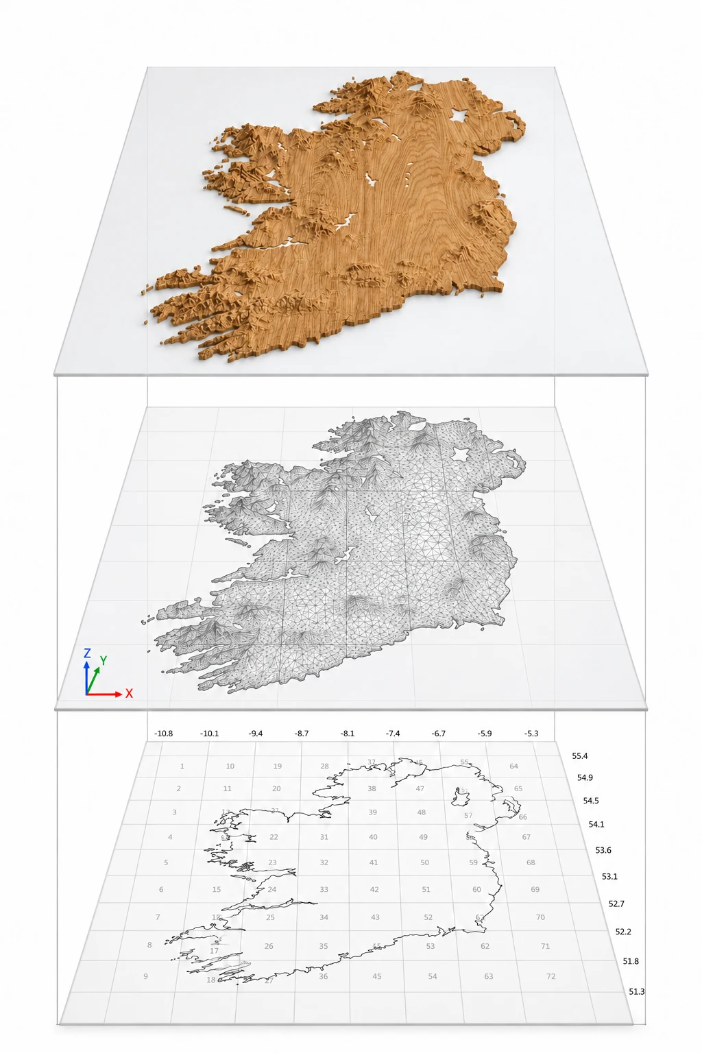
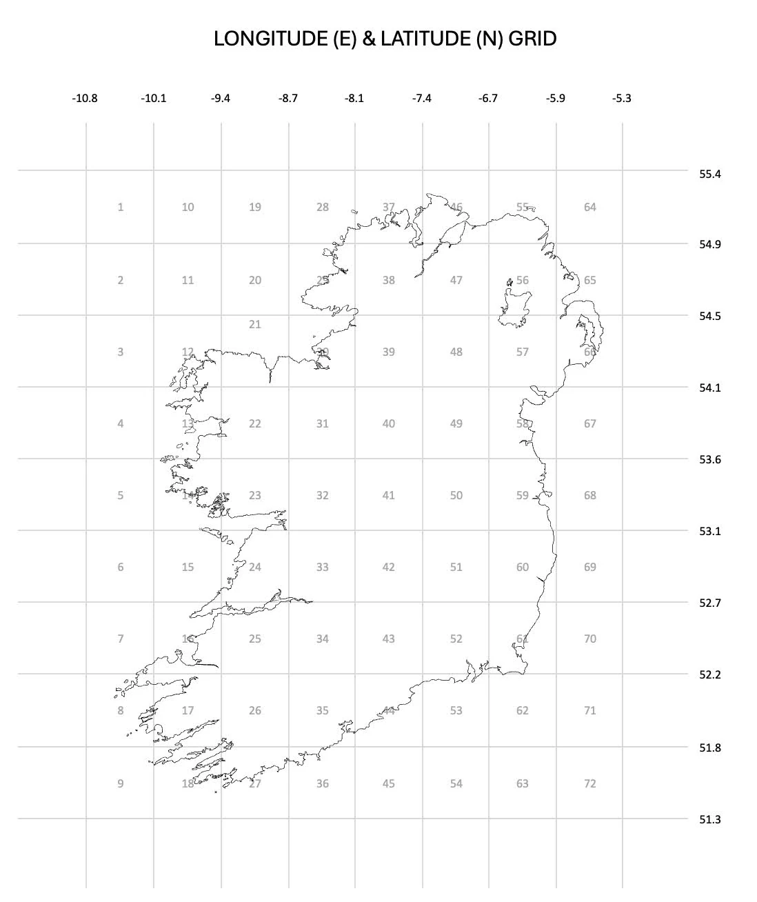
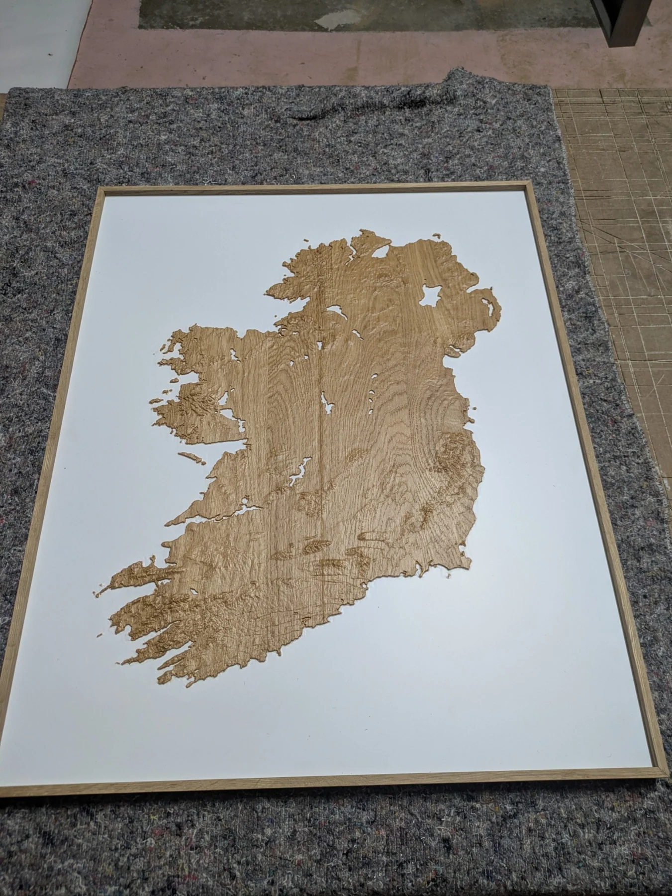
The full island began with a carefully aligned coordinate grid; 8 columns and 9 rows that divided the model into tiles, each covering approximately 50 km in distance.
The first full-island model used six larger sections—two across and three high—based on the same framework.
Why work in sections?
A single mesh of the whole island put too much pressure on the digital software, and reduced resolution by smoothing out the landscape features.
Preparing smaller areas separately and stitching together in the software made it possible to retain a high resolution for the full piece.
02 / Getting the sections to meet
A problem at the edges.
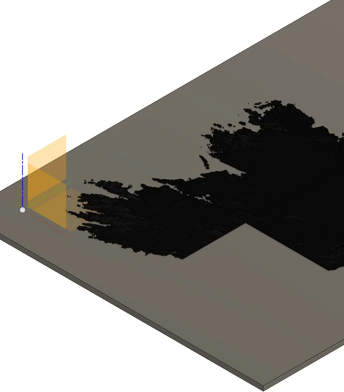
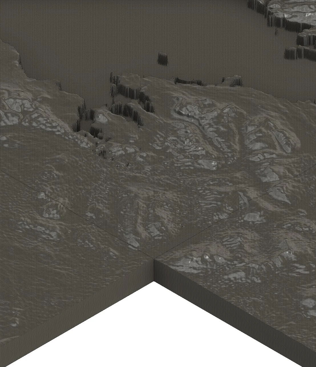
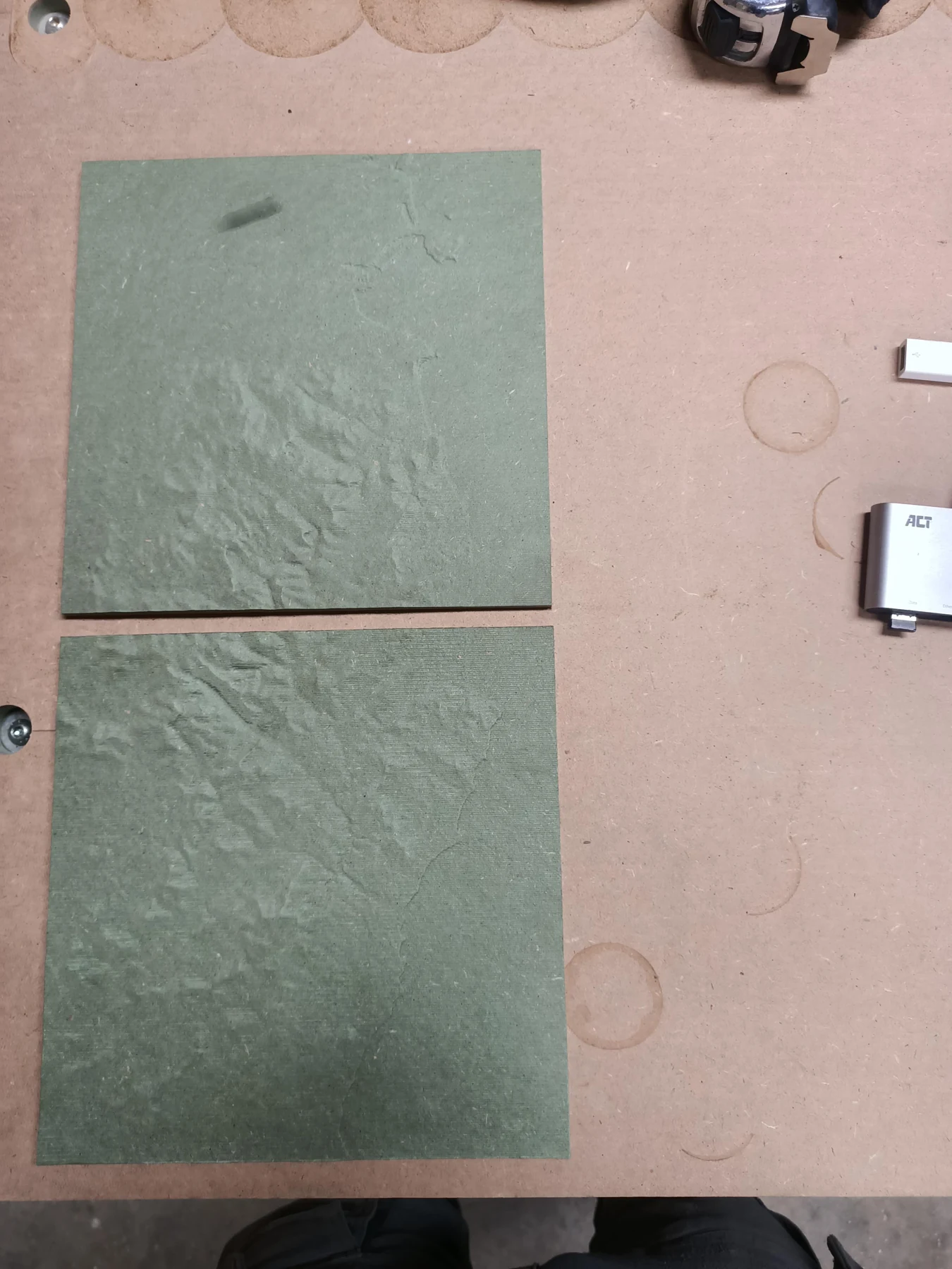
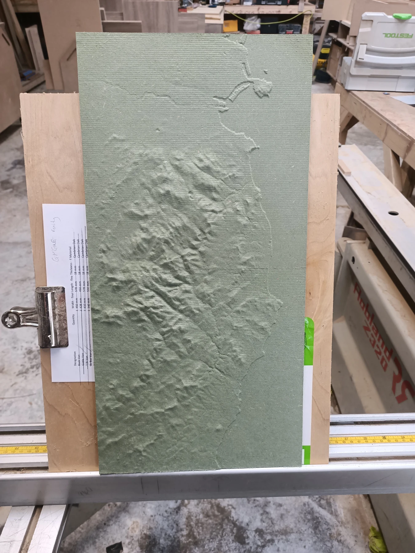
The earth’s curvature presented an unexpected problem. When the terrain was turned into flat tiles, early sections came out wider at the top and narrower at the bottom.
I corrected the way the coordinates were projected, using a Mercator projection to bring adjoining sections into alignment.
See the alignment tests
The test pieces made the mismatch visible. Later sections could be brought together with the terrain continuing across their joins.
03 / Cutting the landscape
Then the wood takes over.
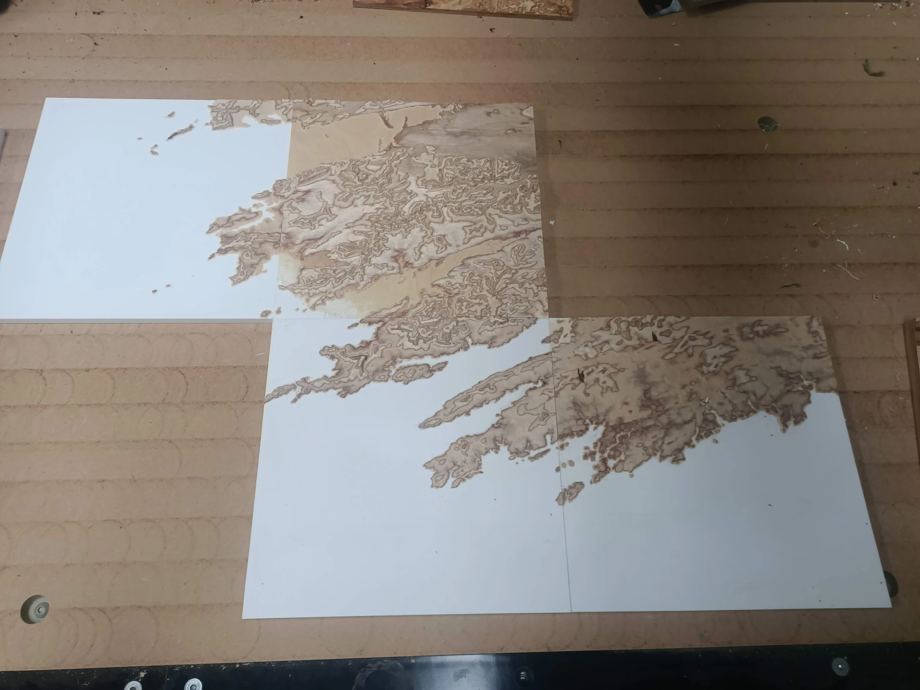
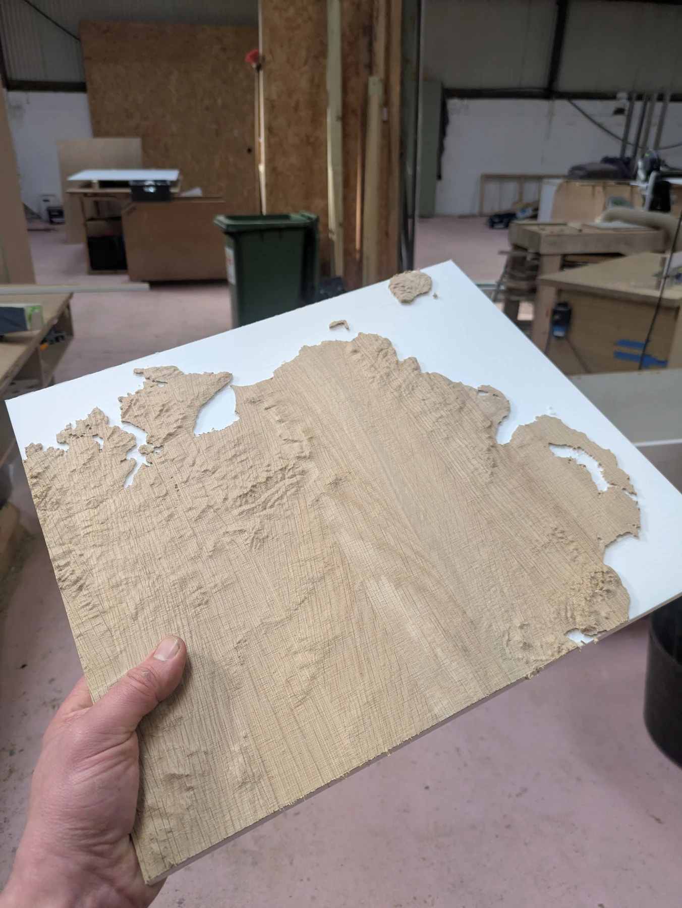
The landscape is machined into the timber with a CNC router. The cuts reveal both the terrain and the character of the wood: grain, colour and, in plywood, the layers within the blank.
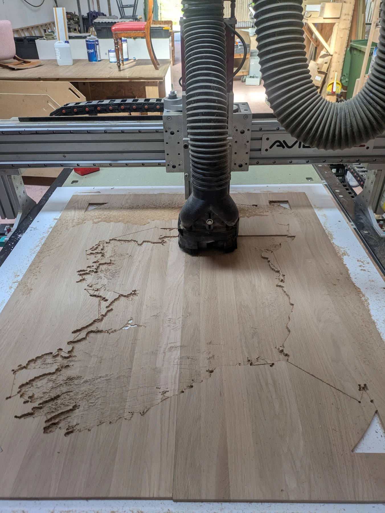
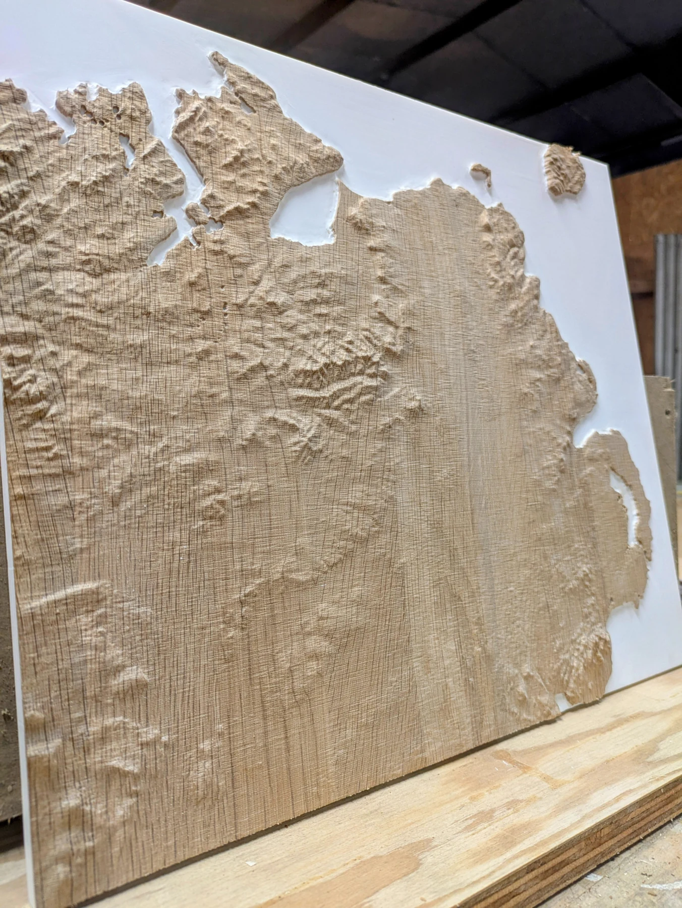
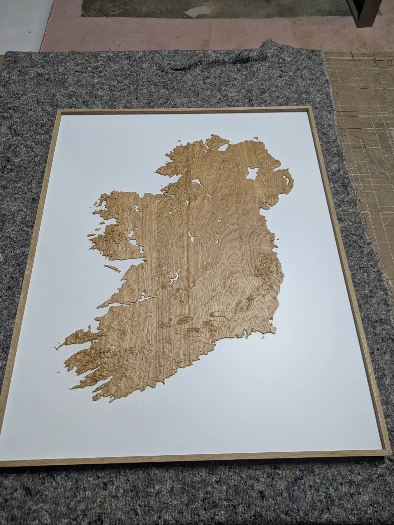
Sanding and finishing complete the work by hand. Light is part of the finished piece too: even a small change in direction can bring different ridges and valleys into view.
What the tests taught me
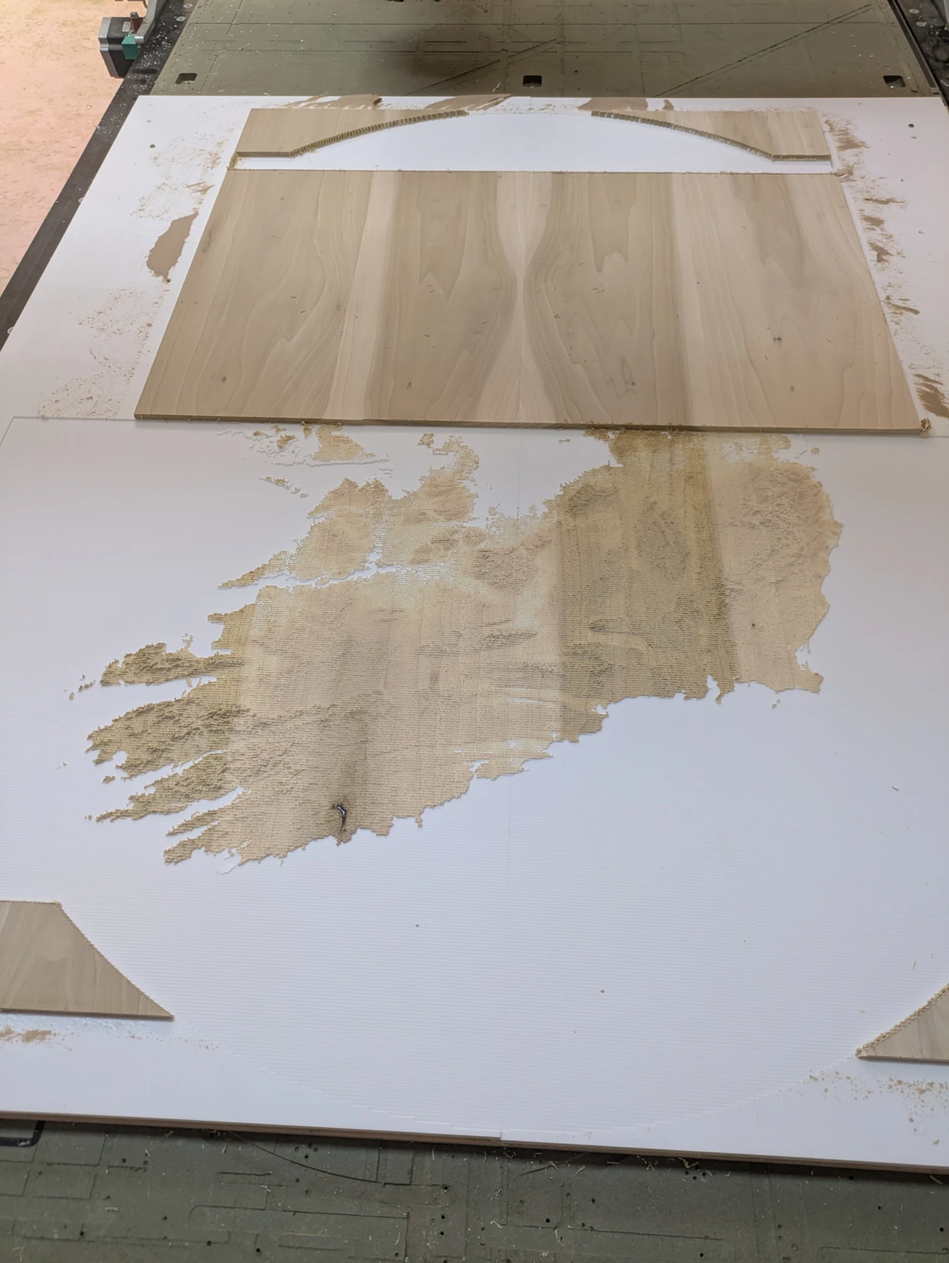
Some cuts exposed problems with the setup or the transition between timber and backing. Test pieces made it possible to work through those problems before committing to the finished model.
Credits
Tools behind the terrain
Digital terrain models generated using TouchTerrain ↗.
Harding, C., Hasiuk, F. & Wood, A. (2021). TouchTerrain—3D Printable Terrain Models. ISPRS International Journal of Geo-Information, 10(3), 108. Published research ↗
Enquiries
An Ireland model of your own.
Get in touch to discuss an Ireland terrain model and what you have in mind.
Discuss an Ireland model